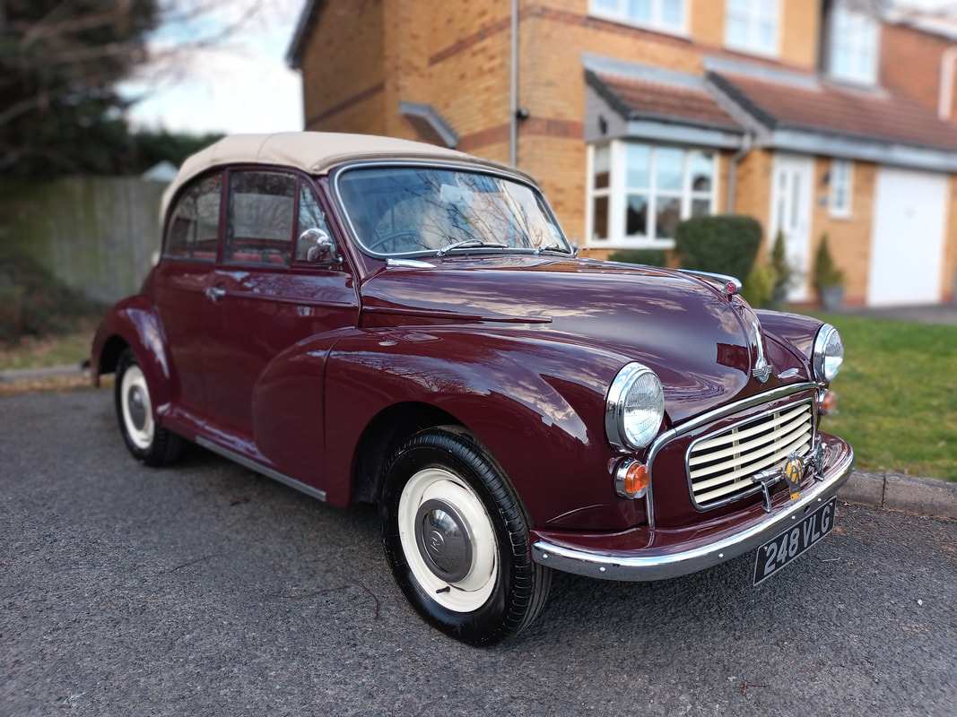
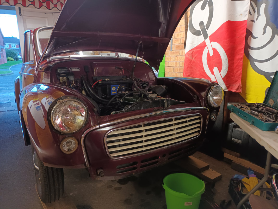
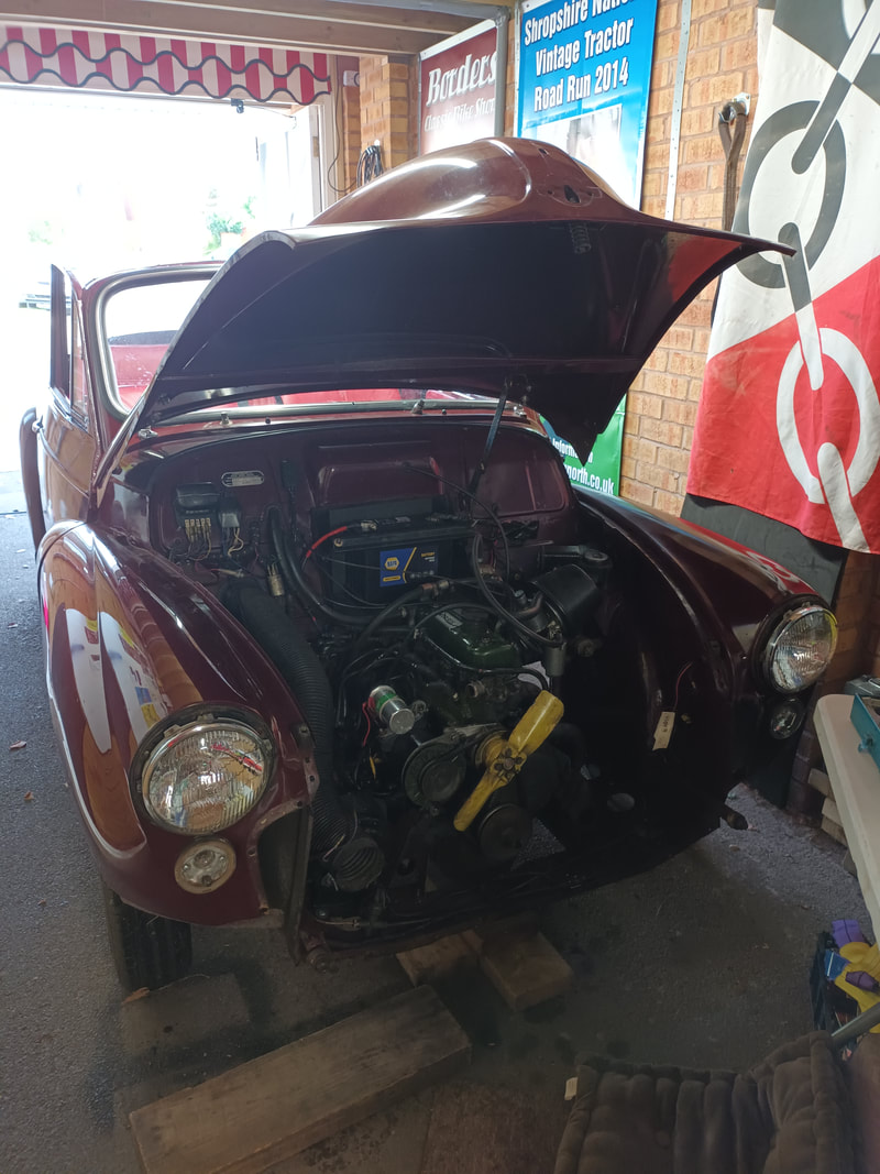
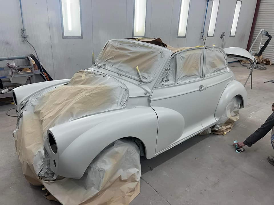
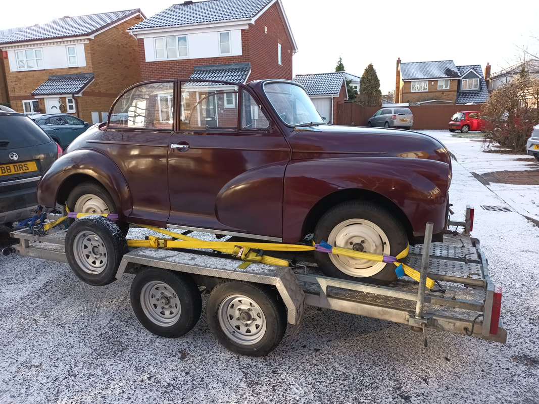
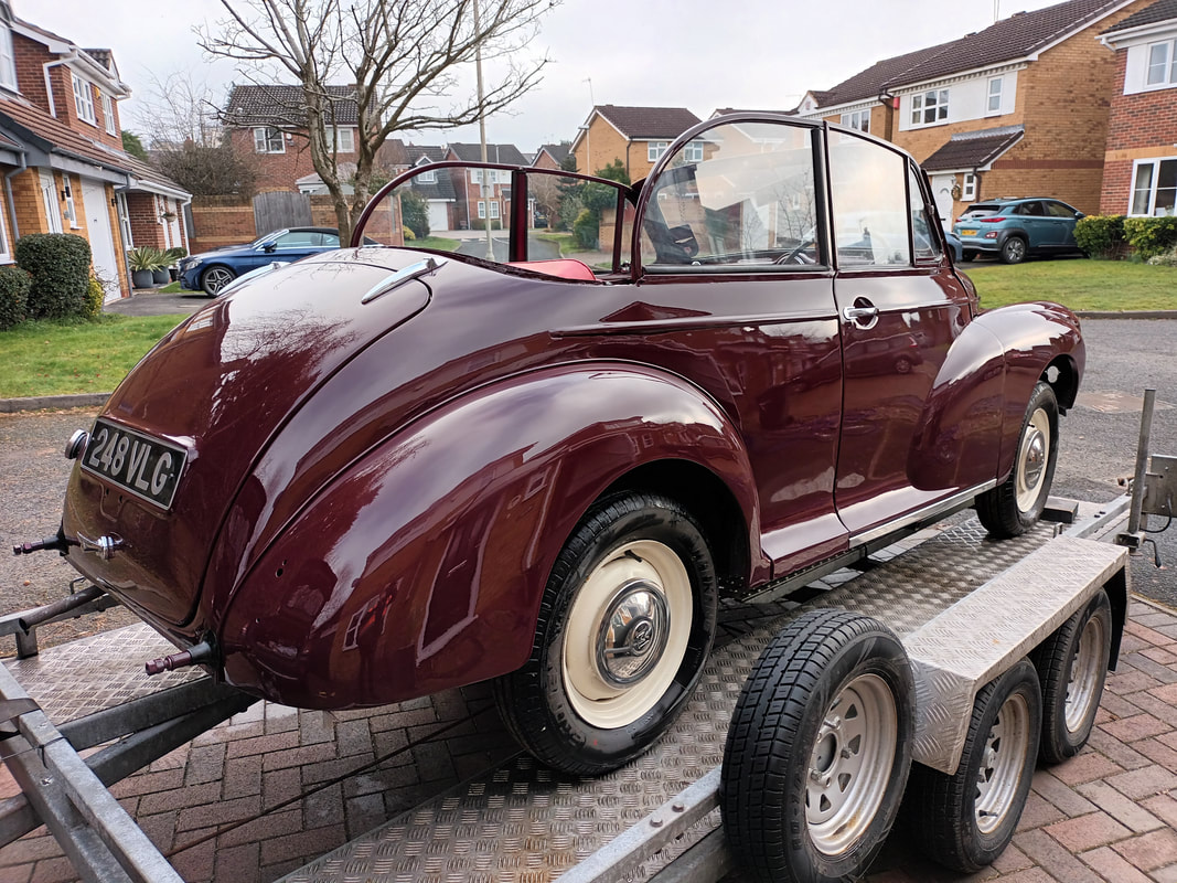
I bought the Minor from a local person who looked after it very well, engine sounded good and it drives very well. The only problem with it was a terrible paint job. The original paint was on most of it but the person I got it from had tried to hand spray with a can in loads of different places and it looked terrible. I got in touch with a friend of mine who owns Wednesbury Car and Commercial painters who looked at the car and went underneath to find that it was pretty much rust free. He gave me a couple of options and I took the strip myself and delivered it to him ready for his team to prepare the body and paint it to a great standard. He had it for a couple of weeks as he was fitting it in between other jobs plus I was paying in paper notes. Fetched it back and it took me just about three weeks to put it all back together and have it driving about . The paintwork now looks amazing , new tyres all around and ready to enjoy some warm and sunny weather .
Kevin Birch 1969 Mk2 Lotus Cortina Engine Rebuild
1969 MK2 Lotus Cortina, Kevin Birch, Oct. 2023
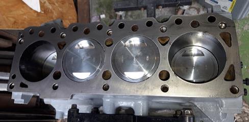
Many will have seen my car on the club stand at the NEC in March 2022, so what has been going on with it since then. The big move forward was getting the engine rebuilt, which has proved costly and a slow process. It was taken in to have the necessary machining done, but this proved to be more complicated than expected. In the past it has been extensively modified, with it being bored out and lined to take the bigger 85mm pistons, over the 83mm standard ones. This was a big mod in the ‘70s to gain considerably more power, but does hike up the compression ratio with which modern fuels can’t cope. There were 2 solutions, either get a thick head gasket (4-5mm) made, or re-line the block back to standard. The head gasket route may not be reliable, and as the 85mm pistons are £150 +VAT each, expensive. Two of the bores needed liners anyway, so it was decided to take it back to standard bore, and fit forged pistons, which were only £100 + VAT each!! The forged steel crank was standard and only needed a polish, the head needed new valves, guides, hardened seats and a skim, all pretty standard stuff.
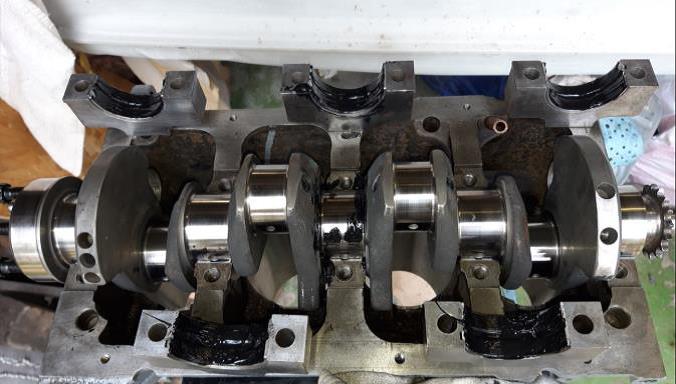
The water pump however was a different matter. It is built into the aluminium front timing cover, and although a repair kit is available to replace it, the timing cover housing was severely corroded, which would have made it virtually impossible to make a watertight seal. In this case there is really only one solution, which means buying a complete new designed timing case, which now has a bolt in water pump, which comes at the princely sum of £700, ouch! This new casting does have the advantage of being able to just unbolt the pump and replace it in an hour or two, whereas the old design means removing the head to do the same job, and with the pumps being a weak spot on the engine, this is a good thing. Once all the machining was done, a trial assembly was made, which showed that the pistons were protruding 2.5 mm above the block at TDC, this was when I realised the crank was from a 1600cc engine, whereas the Lotus is based on the 1500cc engine which has shorter block, and less throw on the crank by 2.5mm. Checking the old pistons against the new, found the old ones had been turned down to fit the block. So, either turn the new pistons down, but as the crank has a longer throw, the compression would increase, or change the crank back to 1500 types as standard, keeping the compression ratio to 9.5:1. A new forged crank was duly purchased, fortunately I got a good price for the old one to offset costs, and when fitted all was good. The flywheel was not in good condition, and rather than have it faced, a new steel one was bought, which is stronger and lighter than the old cast iron one. New problem, the new crank and the flywheel wouldn’t go together, the crank is double doweled for strength, and the holes in the flywheel didn’t quite line up, 1 thou of an inch out, but it was enough. The dowls were pulled out the crank, the flywheel bolted on, and the assembly re-drilled to take slightly larger dowls, at more expense. A new clutch assembly was obtained, this proved to be very difficult, the old clutch disappeared years ago, and the Cortina club will only do exchange units as they are not available new. Burton will supply a brand-new racing clutch at eye-watering cost, but that would not be suitable for road use. I eventually found a full clutch that may fit, the plate had the correct splines and was of the correct diameter, and the measurements of the cover appeared correct, so one was ordered. It all looked good when it arrived, only to find the bolt and dowl holes in the fly wheel were in the correct position, except they were all 1mm further out on the radius to the holes in the cover. So, I decided to have the flywheel machined to take the cover, which needs to be perfectly central otherwise it will destroy the crank bearings. So, thinking all was good, all new bearings, gaskets and seals etc were ordered (up to now I had been using the old bearings to trial assemble it as the crank hadn’t been ground and the bearings fitted) and assembly proper can begin. I ordered the correct gasket sealants, Graphogen assembly paste and Plastigauge to ensure the bearing gaps are within tolerance on assembly, (measure twice build once). All excited and everything cleaned, cleaned again, then cleaned within an inch of its life, assembly started. First off put the main shell bearings in the block dry, fit the crank and put a small piece of Plastigauge across each bearing and put the caps on with the new bearings in them, then torque it all down, ensuring the crank doesn’t rotate. Undo all the caps and remove them then measure the Plastigauge with a special piece of card that comes with it, to determine the running clearance. Plastigauge is like Plasticene, it has a specific diameter and when squashed by the bearings, spreads out, you then determine from how far it spreads with a card gauge what the clearance is. This engine should have between 1.5-2.1 thou” clearance gap, on removing the main cap, the Plastigauge had hardly been touched, with just a small flat indent in the top. Not sure what is going on, re did everything with the same results. Ensuring I’m doing it right, and that the Plastigauge isn’t at fault, I decide to repeat the procedure on the big end bearings, and on removing the caps found the Plastigauge to be squashed as expected, and when measured was 1.7thou” which is bang on where it should be. So, the Plastigauge is right and the procedure is right, but the main bearings still prove to be an issue. I measured the journals with 2 different micrometres, and it was definitely standard, not ground, so the bearings should fit. The bearings had the correct details on the box, but when I fitted the bearings in the caps and then fitted the caps to the block without the crank, I could get a 30 thou” feeler gauge between the two shells. Obviously, the bearings now are at fault, I fitted the crank with the old bearings, and they squashed the Plastigauge to within the correct tolerance, so proving the new bearings to be at fault. On looking closely, the old bearing felt thicker than the new ones, so before getting on the phone complaining about the new bearings being incorrect in the box, something I have never heard of before, I looked up the old bearing number, stamped on the back, on the internet. Not expecting to find anything, as they would have been at least 40years old, and there was the answer. The old bearings, being standard on the crank surface, were 15 thou” bigger on the housing surface, which meant the whole engine block and mains caps had been line bored in the past to align them. There were no markings to suggest this, and so I had to buy another set of bearings, I couldn’t return the other set as they had been opened and had witness marks on them where the crank had touched them. The new bearings duly arrived and all was good with the clearance proving to be 1.7thou” across all the journals, so the bottom end was assembled without further issues.
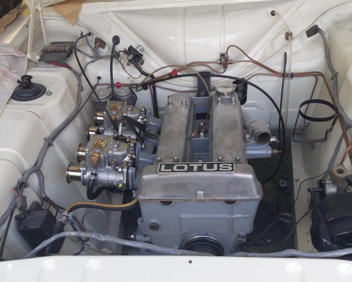
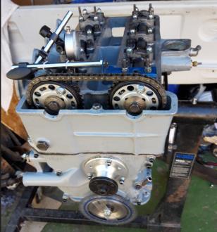
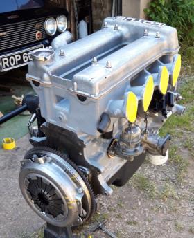
The head was the next thing to put on after spending hours setting the valve clearances, which is done by fitting shims between the valve stem and an upturned bucket that the cam lobe presses on. The procedure is to fit the shims, put the cam in, measure the gap, take the cam back out measure the shim, then do the maths to determine what size shim you need to get the correct clearance. Not a quick job, as you then need to order new shims at the correct thickness, all available in 1 thou increments, then go through the same procedure again, if you are lucky, you get this done in 2 attempts, but it took me 3 as some clearances were still out after fitting new shims. I blame this on the fact that the old shims were used for the first measurement and they have the size engraved on them, I should have really measured them as some were now wrong. With the cams I’m using there isn’t any allowance for the gap, they are 10 thou” inlet & exhaust, and that is it. Now the head can go on which can get tricky as it is a twin overhead design, and now having had the head and block skimmed, means the cam timing will be slightly out if using the original chain sprockets. I have spent too much money and time on making this engine as good as I can, so bought some vernier sprockets which are adjustable so you can get the cams to open at the exact time they’re supposed to. The only issue is that they don’t come with any timing marks. It eventually took me 2 days to get it timed up correctly, it was a very steep learning curve and I had to be really careful that the valves don’t touch the pistons, there is very little clearance near TDC, and if they do, do not to turn the engine any further. They were set up with a dial gauge on the valve stem bucket and protractor set up on the crank, after true TDC had been found, so that the valves opened and closed, at the correct degree of crank rotation, as specified for the camshafts, which in this case are Cosworth CPL2 items. Engine was all painted and ready to go in after the gearbox had been installed, which was an easy job. So, for the first time in 36 years, the engine is back in the car, it isn’t running yet, and I am keeping it that way until nearer the end of the restoration, as it has been assembled with Graphogen which is better for long term storage than oil. Once started the Graphogen will dissolve in the oil, and it will then go for an immediate rolling road tune up, so that the carbs are set correctly, as it is very easy with these carbs to over fuel and damage the engine quickly. So now the engine is back to standard bore, has a forged steel crank, CPL2 cams, lightened steel flywheel and front pulley, forged pistons, polished and radiused conrods, ARP big end and crank bolts, steel main bearings and has been fully balanced and topped with a big valve ported head. So should be able to rev to 8000 RPM, whether the 40COEs can provide that much air, I don’t know. I won’t take it that high but knowing it has some headroom above the standard 6500 RPM limit will be good. I expect BHP would be around 130 to 140, over the standard 108 quoted by Ford at the car’s launch, the rolling road will see. Just need now for my wallet to recover as it has cost twice what I budgeted for